Solar Panel Micro-Crack & Electroluminescence (EL) Guide Pakistan 2026: Hidden Cell Defects
By PSI Editorial · 18 min read · Updated September 2026
🔬 Micro-Crack & EL Fast Facts (Pakistan 2026)
- The "X-Ray" Diagnostic: Electroluminescence (EL) at 1,150nm Near-Infrared reveals invisible silicon cracks.
- The Cleaning Sin: Walking or resting body weight on panels shatters the 140-micron silicon wafer underneath.
- Long-Term Threat: Hairline fractures evolve into isolated dark dead cell fragments and 140°C hotspots.
- Standard Compliance: IEC 61215 Mechanical Load & IEC TS 60904-13 EL Certified.
Atomic Summary: A solar panel can appear 100% pristine, shiny, and undamaged to the naked human eye, while its internal silicon wafers are shattered into thousands of microscopic fractures. In Pakistan's harsh logistics and installation environment, micro-cracks are the leading cause of unexplained power degradation and dangerous rooftop hotspot fires. Master Electroluminescence (EL) testing and defect classification.
Optoelectronic Physics: The Near-Infrared (1150nm) Radiative Recombination Emission
A solar cell is fundamentally a large-area PN junction diode. When operated in reverse (injecting current instead of extracting power):
- Forward-Bias Current Injection: A DC bench power supply injects forward-bias current equal to the panel's rated Short-Circuit Current (I_sc ≈ 14) in a dark testing enclosure.
- Band-to-Band Radiative Recombination: Injected electrons recombine with holes in the active silicon p-n junction, releasing energy equal to the silicon bandgap (E_g = 1.12) as Near-Infrared (NIR) photons at λ = 1,150.
- The EL Image Contrast: Electrically active silicon emits strong NIR light (appearing bright glowing white on a specialized InGaAs sensor). Where a micro-crack has severed the electrical contact finger, zero current flows — resulting in zero photon emission and creating a jet-black shadow or inactive dark void!
Classification of Micro-Cracks & Long-Term Degradation Risk
| Micro-Crack Classification | EL Visual Appearance | Electrical Continuity | 5-Year Degradation Risk | Pass / Fail Criteria |
|---|---|---|---|---|
| Class A (Hairline Micro-Crack) | Thin hairline black line across cell; zero dark inactive area. | 100% Connected (All fingers conducting) | Moderate (<% power loss) | ACCEPTABLE (Monitor annually) |
| Class B (V-Shaped / Cross Crack) | Multiple intersecting diagonal cracks with grey dimmed cell zones. | Partial contact degradation | High (5%–10% power loss) | MARGINAL (Downgrade to B-grade) |
| Class C (Dead Isolated Inactive Fragment) | Jet-black triangle or corner fragment (>10% of cell completely dark). | Zero Continuity: Completely severed from busbars. | CRITICAL: Severe Hotspot (>140°C) & Fire Hazard! | REJECT & REPLACE IMMEDIATELY |
The 4 Golden Rules to Prevent Micro-Cracks in Pakistan
- NEVER Step, Walk, or Kneel on Solar Panels: Instruct cleaning staff that standing on the glass destroys the 140-micron silicon wafer underneath. Always use long-reach telescopic carbon fiber cleaning poles.
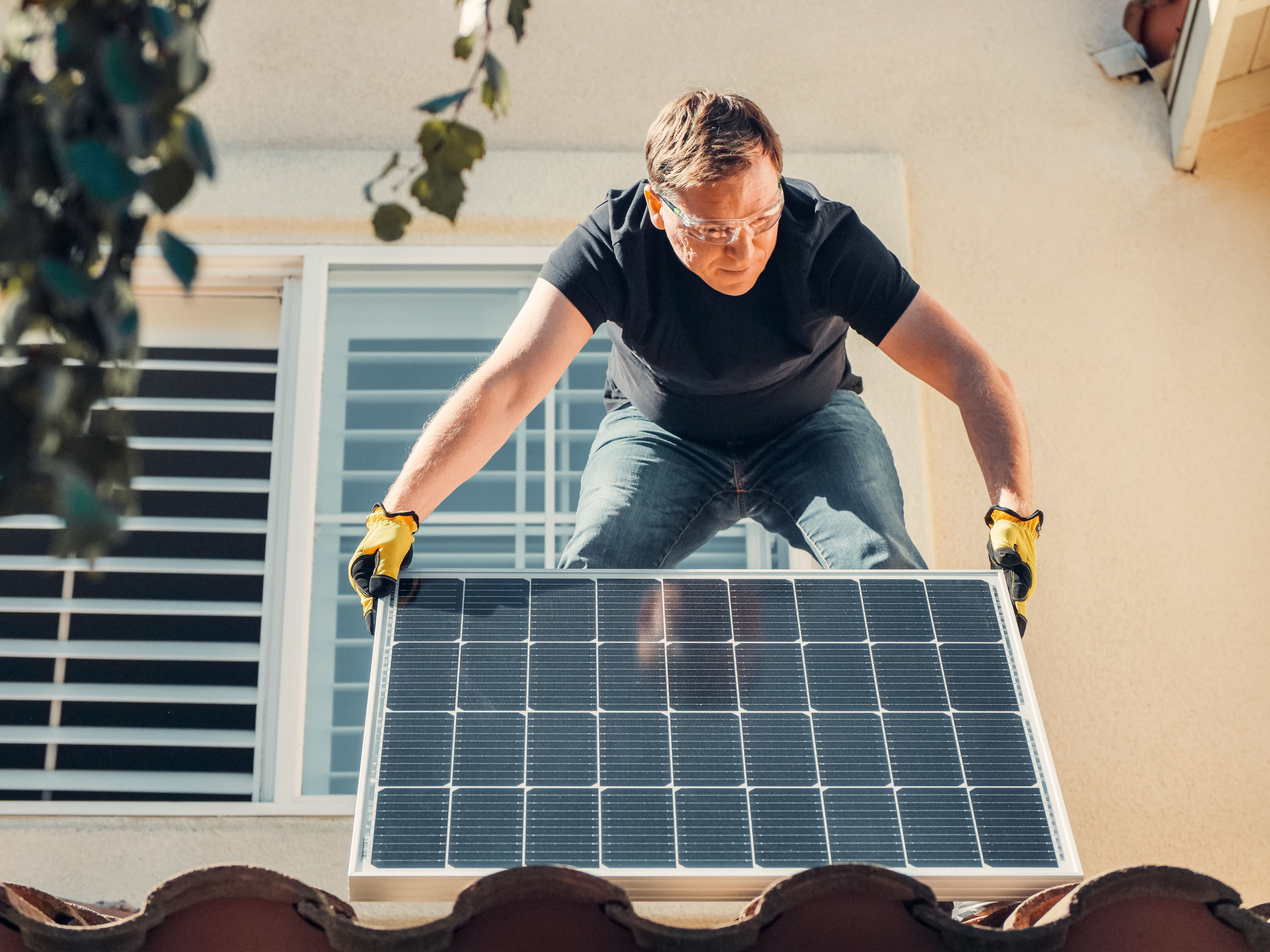
- Two-Person Handling During Installation: Never lift a 585W panel (measuring 7.5 feet long and weighing 28 kg) by one corner. Always lift with two technicians gripping the center aluminum frame to prevent torsional frame twisting.
- Vertical Pallet Truck Transport with Corner Protectors: When transporting panels from Karachi port to interior Punjab/KPK, ensure panels remain strapped vertically inside factory wooden crates with cardboard corner protectors. Never stack loose unboxed panels horizontally on top of each other in open pickup trucks.
- Torque-Controlled Frame Clamping: Use a calibrated torque wrench set to 8 to 10 Nm on mid-clamps and end-clamps. Over-tightening clamps with pneumatic impact guns causes localized point-load micro-cracking directly beneath the clamp edge.
Frequently Asked Questions
Can Electroluminescence (EL) testing be conducted during the daytime?
EL testing requires complete darkness because ambient sunlight is 10,000x brighter than the faint NIR photon emission. Mobile testing is conducted at night on rooftops using portable high-sensitivity cameras or inside specialized dark testing trailers during the day.
How can you distinguish factory micro-cracks from installation damage?
Factory transit cracks typically follow wafer crystal cleavage planes (straight 45° or 90° lines). Installation footstep damage displays distinctive concentric circular spiderweb cracks centered on the point of human foot impact.
Related: Thermal Imaging Guide · PID Degradation Guide · Solar Calculator